Pass Filter Circuits Quickly Circuit Diagram Active Low Pass Filter Example No1. Design a non-inverting active low pass filter circuit that has a gain of ten at low frequencies, a high frequency cut-off or corner frequency of 159Hz and an input impedance of 10KΩ. The voltage gain of a non-inverting operational amplifier is given as:
Whether you're designing an entire sound system complete with a bass boost, or just want to remove high-frequency noise, the low-pass filter calculator can help you create the perfect low-pass filter circuit for your needs. Read on to learn: What a low-pass filter is; The difference between passive and active low-pass filters; and
PDF Active Low Circuit Diagram
A low-pass filter (LPF) is designed to pass all frequencies below the cut-off frequency and reject all frequencies above the cut-off frequency. It is simply an RC series circuit across the input, with the output taken across the capacitor. At the cut-off frequency, the capacitive reactance of capacitor C is equal to the resistance of resistor R, causing the output voltage to be 0.707 times the
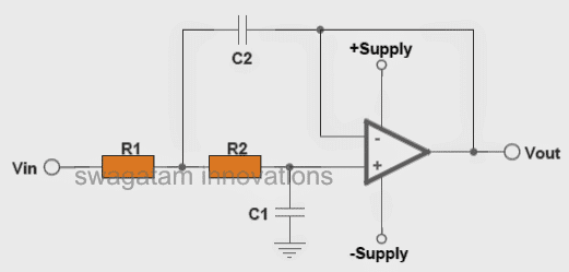
To surmount this problem, active circuit designs were introduced. When a passive low pass filter is connected to an Op-Amp either in inverting or non-inverting condition, it gives an active low pass filter design. The connection of a simple RC circuit with a single Op-Amp is shown in the image below.. First Order Active Low Pass Filter with the frequency response The formula and schematic for the LC low pass filter: Let's analyze a low pass filter with a practical example : Q. Design a low pass filter having cutoff frequency 'fc' = 75MHz and Vin = 5 volts using RC filter? Solution: given -> f = 75Mhz. R = 100 Ω(assumed)——-
Low Pass Filter Calculator Circuit Diagram
This article explores the analysis and design of passive low-pass filters. These circuits play an important role in a wide variety of systems and applications. The RC Low-Pass Filter We can attempt to create a second-order RC low-pass filter by designing a first-order filter according to the desired cutoff frequency and then connecting two
