Figure A2 Schematic of the used electrical components of the resistive Circuit Diagram Once you understand how a voltage drops over a resistor, you're about halfway done with understanding a voltage divider. If you need a voltage lower in your circuit than the voltage that is provided by your power source, you can use a voltage divider. a potentiometer is a voltage divider that changes the resistance values depending on

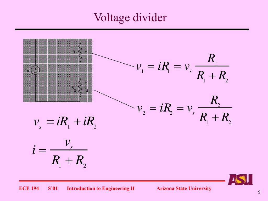
In electronics, a voltage divider (also known as a potential divider) is a passive linear circuit that produces an output voltage (V out) that is a fraction of its input voltage (V in). Voltage division is the result of distributing the input voltage among the components of the divider. A simple example of a voltage divider is two resistors connected in series, with the input voltage applied
Basic Electronics Tutorials and Revision Circuit Diagram
A voltage divider is a simple circuit that can reduce voltage. It distributes the input voltage among the components of the circuit. The best example of a voltage divider is two resistors connected in series, with the input voltage applied across the resistor pair and the output voltage taken from a point between them. It is used to produce different voltage levels from a common voltage source
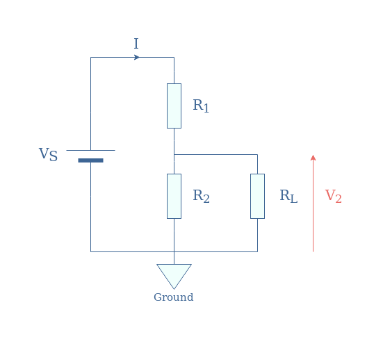
Voltage Divider. The two resistor voltage divider is used often to supply a voltage different from that of an available battery or power supply. In application the output voltage depends upon the resistance of the load it drives. where is the parallel resistance of R 2 and the load resistor R L. For : R 1 = Ω, R 2 = Ω, and V 1 = V, Understanding Voltage Dividers. A voltage divider works on the principle of ohm's law, which states that the voltage across a resistor is proportional to the current flowing through it and the resistance of the resistor.By selecting the appropriate resistor values, a voltage divider can be used to scale down a high voltage to a lower voltage, making it suitable for a wide range of applications.
![Design a resistor voltage divider [Step by step 2025] Circuit Diagram](https://www.yamanelectronics.com/wp-content/uploads/2022/11/resistor-voltage-divider-circuit-example.png)
How Voltage Dividers Work Circuit Diagram
Circuits that consist of voltage dividers allow many voltage levels to be generated from a single voltage source.This source may be a voltage of +5V, +12V, -5V, or-12V, or it may be a negative voltage with respect to ground (0V).A dual supply, consisting of positive and negative voltages such as ±5V or ±12V, is another option.. Voltage dividers are sometimes referred to as potential dividers.