DC Voltage Step Down Regulator Circuit Diagram It has a 1.25V reference regulator part that also looks like the LM317. We can connect to the output to monitor the voltage and maintain stability. Well, it may be enough. You might start to get bored. 1.5V Switching Regulator circuit using KA34063. Next, Let's make a 1.5V Step-up Switching regulator circuit.
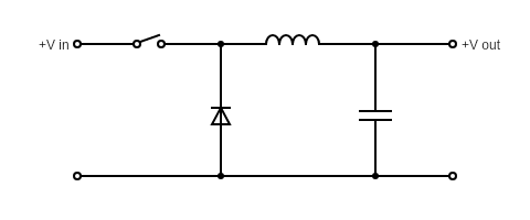
The major function of the voltage regulator is to drop the higher voltage into lower or the increase lower voltages into higher, that's why known as step down voltage regulator or step-up regulator respectively. However, many other types of voltage regulators also have been designed by circuit designers and engineers. Last Updated on March 16, 2024 . Simple Step down Voltage Regulator Circuit designed by using IC LM2678. This Circuit takes 8 volt to 40 volt as input and gives 5 volt / 5 Amps Regulated DC as output. IC LM2678 from Texas Instruments is monolithic Integrated circuit which provide all of the active functions for Step down (buck) switching Regulator. This is known as a buck or step-down converter. Figure 1. Buck (step-down) converter simulation schematic . The buck or step-down converter can be used to accomplish a common task for power-management circuits: reducing a standard system-level voltage, such as 12 or 28 V, to a 5 or 3.3 V supply rail that is appropriate for low-voltage electronics.
PDF Application Note 35 August 1989 Step Circuit Diagram
A buck converter or step-down converter is a DC-to-DC converter which decreases voltage, while increasing current, Both static and dynamic power losses occur in any switching regulator. Another technique is to insert a small resistor in the circuit and measure the voltage across it. This approach is more accurate and adjustable, but
A buck converter, also known as a step-down converter, is a high-energy efficiency DC-to-DC converter that steps down the input voltage to a lower output voltage while maintaining the same polarity. It uses lossless components like inductors, capacitors, and switches to achieve high efficiency. Output voltage regulation is achieved using PWM Figure 2. Conceptual Feedback Controlled Step-Down Regulator Practical Step-Down Switching Regulator Figure 3, a practical circuit using the LT ®10742 IC regulator, shows similarities to the conceptual regulator. Some new elements have also appeared. Components at the LT1074's "VCOMP" pin control the IC's frequency compensation, Step-Down Adjustable Voltage, Current Regulator Circuit using LM2673. Last Updated on February 7, 2025 by Swagatam Leave a Comment. (20V to 28V) to step down the voltage to a more normal 14.8V for gadgets. And, say those gadgets need 2A max. Step 2: Pick an LM2673S-ADJ. To get that output voltage to 14.8V you'll need a couple of resistors