Cooling Fan 2 Control Circuit Open Wiring System Circuit Diagram The microcontroller was programmed to automatically control the fan's regulator with the aid of the relays. The relay automatically swings into action individually to control the fan's regulator. The fan's regulator is configure off, low, medium and high with respect to 25 oC, 28 oC, 31 oC and 33 oC temperature for an automated control

Then we will check if the temperature value is greater than 35 or not, if the temperature will be greater than 35, then the relay will be activated and the fan will start to rotate. Hardware Part First of all, make the connection of the LCD module with the Arduino as follows:
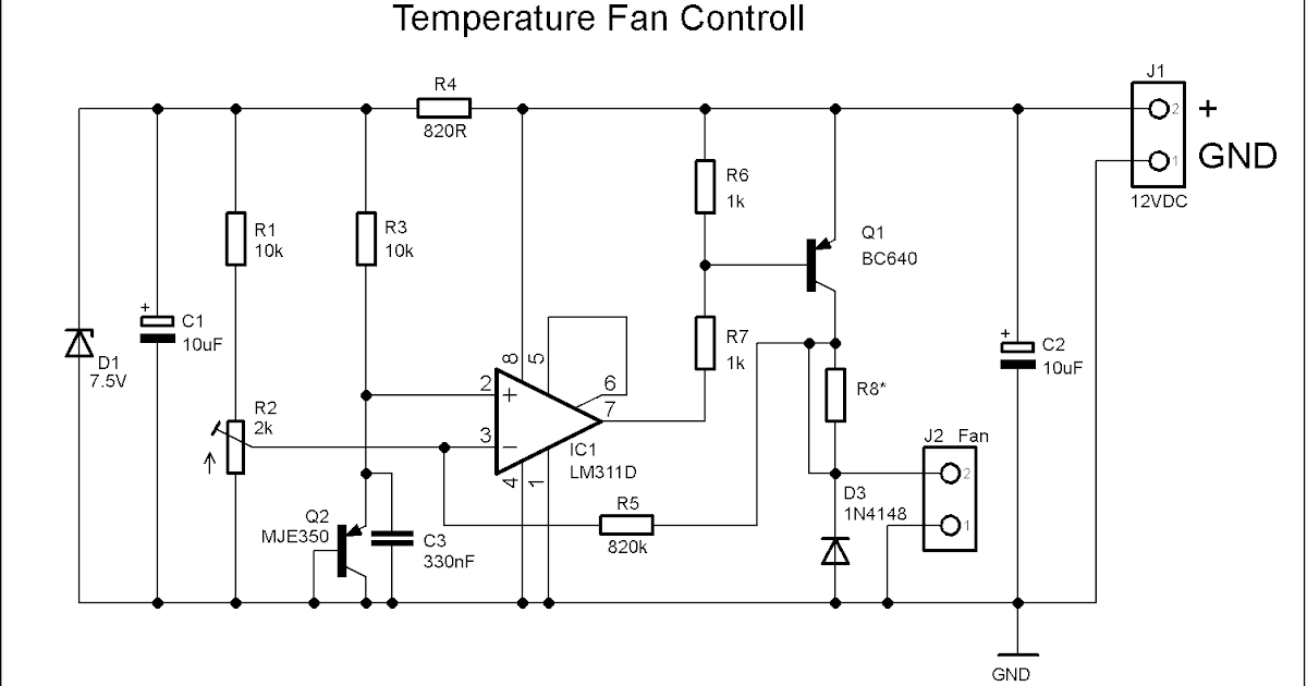
Temperature Controlled Fan using Arduino Circuit Diagram
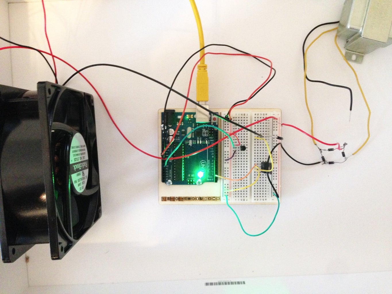
Working of Automatic Temperature Controlled Fan. The described project is a temperature control system that utilizes an LM35 temperature sensor, an Arduino microcontroller, and a relay to regulate an AC fan based on the ambient temperature. This action provides a cooling mechanism to maintain the temperature within the desired range. In the
In this article, we learned about, how we can make a temperature-controlled fan circuit. Using an Arduino, DHT11, and few other components. Which can be used pretty much any place where temperature needs to be maintained at specific levels. Like in some industries, houses, etc. Some of these uses active cooling method, by using a fan on heatsink which help to remain the temperatures more stable. But when running these things on a low power fan is still on and feel noisy. So why not to make a programmable fan which can be turned on when required. Using Arduino and temperature sensor we can make a temperature-controlled

Controlled Fan Using Arduino Circuit Diagram
But at present to overcome this manual operation, an automatic temperature-controlled fan. This circuit works with a 12V DC fan. Required Components. The required components of this circuit mainly include; a 12V power supply, 10K NTC, IRFZ44 N channel MOSFET, a 12V Cooling fan, and a 10 kΩ potentiometer.